(英文)] Kazuya ITOH1,Fumitaka ARAI2,Naoaki SUEMASA1,Satoshi TAMATE3,Toshiyuki KATADA1 (1.Dept.of Urban and Civil Engineering,Tokyo City University,Tokyo,Japan; 2.Geodesign Co,Ltd.,Tokyo,Japan; 3.Construction Safety Research Group,National Institute of Occupational Safety and Health,Japan(JNIOSH),Tokyo,Japan)
(1.Dept.of Urban and Civil Engineering,Tokyo City University,Tokyo,Japan; 2.Geodesign Co,Ltd.,Tokyo,Japan; 3.Construction Safety Research Group,National Institute of Occupational Safety and Health,Japan(JNIOSH),Tokyo,Japan)
备注
临时结构房屋的抗震性能次于永久结构房屋。桩基支撑的塔式起重机是一种临时结构,常被应用于建造高层建筑。安装在高处的塔式起重机,因其是高柔结构,在强地震动的作用下很可能会产生剧烈震荡。桩基结构的地震响应特性受周围的地基和基础类型的影响也较大。在当前日本的设计规范中,地震荷载仅仅被定义为20%的起重机结构重量,都没有充分考虑待结构的动态不稳定性和周围的地基类型。为探究塔式起重机在软粘土桩基中的抗震特性,开展了一系列的离心振动台试验。为起重机吊臂制定了2种不同的荷载条件来准确地模拟实际情况。根据测试结果,对塔式起重机的动力响应行为和影响的因素进行了讨论,得到如下结论:起重机臂架的荷载条件对桩的损伤程度有显著影响,并可以导致塔式起重机不同的破坏模式。
:Earthquake resistance of temporary structures is inferior to that of permanent structures.A tower crane supported by a pile foundation,which is one of the temporary structures,is often used when constructing high-rise buildings.The tower crane installed in a high position may be vibrated largely by strong seismic ground motion because of its slender structure.Dynamic response characteristics of the structure with a pile foundation are greatly influenced by the surrounding ground and the foundation type as well.In current Japanese design mode,however,the seismic load is only to be defined as 20% of the weight of a crane,neither dynamic unstability of the structure nor influence of the surrounding ground type is sufficiently considered.In this paper,a series of centrifugal shaking table tests was performed to investigate the seismic characteristics of the tower crane supported by a pile foundation in soft clay.Two different weight conditions were set for the crane jib to accurately simulate practical situations.From the test results,the dynamic behaviours of the tower crane and the influenced factors were discussed.In addition,it was concluded that the weight conditions for the crane jib give significant influence on the level of pile damage and might lead to different failure patterns of the tower crane.
Introduction
A tower crane supported by a pile foundation is installed on the outside of a structure during construction when it cannot be installed in the inside.The pile foundations have been designed based on the standard of the building constructor because there are no design guidelines on pile foundations of the tower crane.However,even a temporary structure such as a tower crane can cause large damage if it over-turns due to an earthquake.Therefore,it is necessary to clarify the earthquake resistance of the tower crane and determine the design standards of a pile foundation.The dynamic response characteristics of tall structures are influenced by the vibration characteristics of the related factors such as structure,a pile foundation and a surface ground.Furthermore,the rigidity of the ground surrounding the pile foundation may deteriorate during the seismic ground motion and eventually the structure may become unstable.Therefore,when determining the structural stabilities,the interaction between the ground and the structural system has to be taken account,especially in case of soft clay ground which is weak against vibration.Generally,the earthquake-resistance of a tower frame structure used during construction works is smaller than that of the permanent structure because it is only temporarily used and its structure is likely to be designed without considering seismic vibration to minimize construction costs.However if the temporary tower crane is struck by an earthquake,there is a strong possibility that the resulting damage may affect not only the construction site but also the surrounding houses and passersby.In fact,there was a serious accident during the Chi-Chi earthquake in Taiwan where a climbing jib crane fell to the surface ground from a height of 260 m and five people died.In this case,the climbing jib crane,installed on the top of a skyscraper under construction,was thought to be damaged by the unexpected strong vibration due to the large earthquake.According to the design code of the crane,an earthquake load is assumed to be 20% of vertical load.However,in the case of a strong earthquake,the assumed maximum earthquake load on a tower crane may be exceeded because of its unstable slender structure.Therefore,it is essential to analyze the dynamic characteristics of the tower cranes to prevent any damage.The effect of loading conditions on the response characteristics have been analyzed through the previous centrifuge testing of tower crane.In this paper,to develop an understanding of its dynamic behaviors,a model tower crane supported by a pile foundation in soft clay was investigated by using dynamic centrifugal shaking table tests.
1 Centrifuge Model Tests
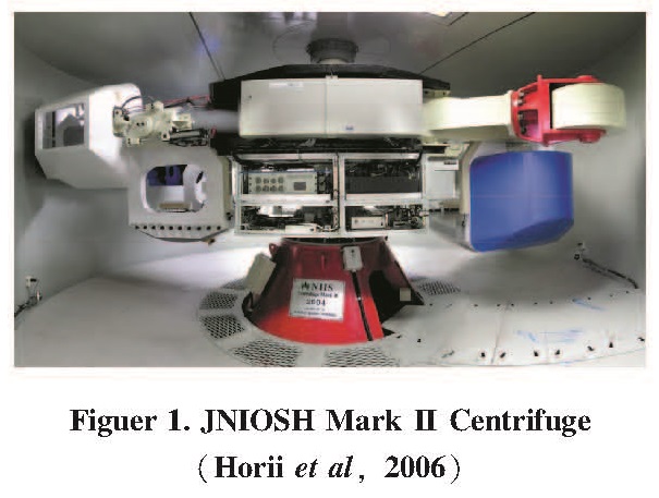
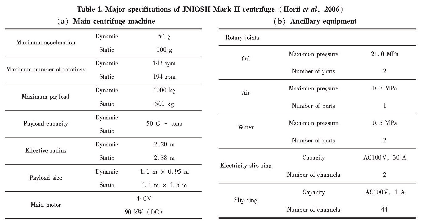
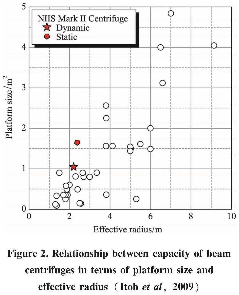
1.1 Centrifuge Facility and Model ContainerAll the tests described here were conducted on the JNIOSH Mark II Centrifuge(Horii et al,2006)owned by the National Institute of Occupational Safety and Health,Japan(JNIOSH),as shown in Figure 1.Technical specifications of JNIOSH Mark II Centrifuge are listed in Table 1.Unlike in other centrifuges,its arms(forms)are asymmetric,which is one of its special features.One side of the arm is provided with a bridge plate where a swinging platform is fixed to its inner end plate with the help of a pair of hydraulic suspension jacks when the platform is lifted up(Dynamic platform).In order to balance this portion(weight of the end plate)of the dynamic side arm while swinging,two counter weights are overhung on the two sides of opposite arm which is used for non-shaking or static tests(Static platform).Figure 2 shows the relationship between capacity of beam centrifuge in terms of platform size and effective radius of rotation.As seen in the figure,in the type of middle size centrifuge used here,longer radius and larger platform could be obtained,equivalent to those of large size centrifuges.In this research,dynamic platform was used for the model test.
Figure 2.Relationship between capacity of beam centrifuges in terms of platform size and effective radius(Itoh et al,2009)The aluminum model container is 450 mm in width,200 mm in breadth,and 347 mm in height.The inner side of the container was anodized to reduce wall face friction.The front face of the container is a transparent window to observe the deformation of the model ground.Two sponges(260 mm in height,200 mm in breadth and 10 mm in thick)were placed near both sides of the container to absorb the stress due to the side boundaries.Effectiveness of the sponges is unknown,nevertheless,comparing the stiffness of the sponges to that of the aluminum wall,the stiffness of the sponges is far similar to that of the soil.Therefore,installing the sponges may absorb the influence of the boundary conditions.
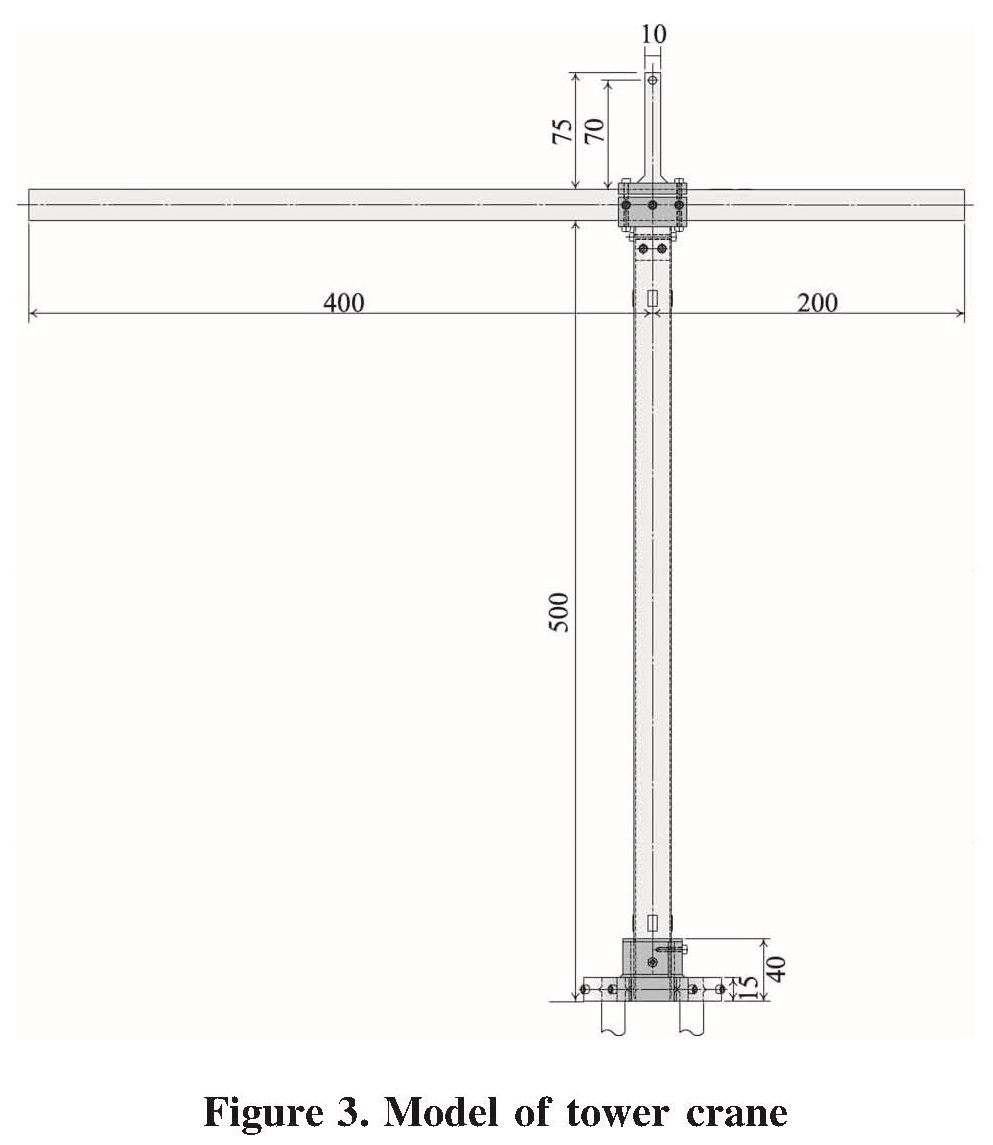
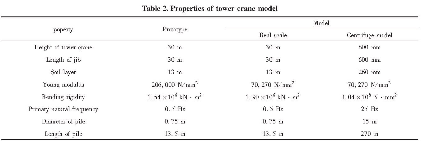
1.2 Modelling of Tower Crane and Pile FoundationIn this study,a hammerhead type of tower crane,which has a simple figure relatively easy to grasp the seismic behaviors,was modeled as the superstructure of the model tower crane as shown in Figure 3.Sizes and materials of the model tower crane were determined by considering the similarity rules for centrifuge modelling.Properties of the model tower crane are listed in Table 2.Previous studies by Itoh et al(2004)and Arai et al(2006a,b)were carried out under different weight conditions of the crane jibs to simulate the actual phenomenon accurately.In this study,similarly to their previous studies,there were two cases of the test set up with different weight conditions for crane jib to accurately simulate practical situations.One was the case of “Balance” which corresponded to the crane having no load and the other was “Unbalance” suspending the loads.In both cases,the total weights of the crane jibs were arranged to be the same.In order to deepen the understanding of properties of the tower crane,different waves,model piles and model ground were set up for the tests.
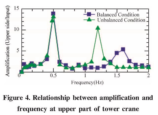
The natural frequencies of the model tower crane were investigated by a resonant search test in 1 g field.The dynamic acceleration of the model tower crane was horizontally recorded by an accelerometer located at upper part of the tower crane.Figure 4 shows the relationship between the amplifications and the frequency in the resonant search test.The first and the second natural frequencies were 0.5 Hz and 1.6 Hz in the case of the balanced condition and 0.5 Hz and 1.2 Hz in the unbalanced condition,respectively at prototype scale according to the peak values of amplification.
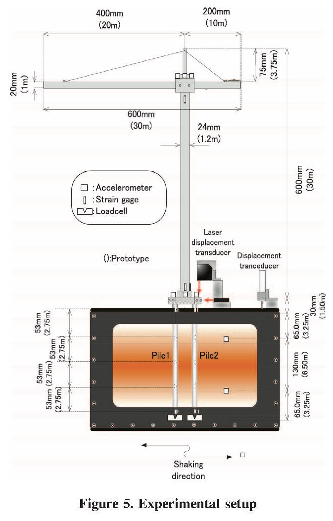
The model substructure of the tower crane has four model piles fixed in the aluminum footing.The pile spacing to diameter ratio was s/d=3.33 in the excitation direction and s/d=4.00 in the transverse direction of shaking axis.Pile 1 was installed in the main-jib side and Pile 2 was installed in counter weight side,as shown in Figure 5.The model pile was approximately equivalent to bending rigidity of a solid concrete pile with a diameter of 800 mm at prototype scale Considering the similarity rule for centrifuge modelling,the aluminum tubes with an outside diameter of 15 mm,thickness of 1mm,and length of 309 mm were used for the model piles.
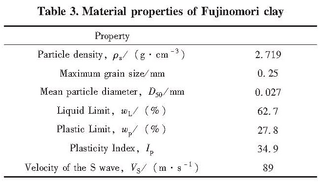
1.3 Experimental ProceduresFujinomori clay was used for the model clay layer in this test because it is well-characterized in the research by Japan Geotechnical Society(1993),as shown in Table 3.De-aired slurry of the clay,which was prepared at 70% water content,was first consolidated in a strong box on the laboratory floor under a pressure of 50 kPa.Then the model piles were installed
in the model ground by using a template in order to insure the location and verticality.All instrumentations were set and centrifugal acceleration was applied up to 50 g allowed for self-weight settlement of the soil.Then,after the excess pore pressure in the ground disappeared,a shaking table test was carried out.Two cases of different weight conditions for the crane jib were investigated in this test as mentioned above.
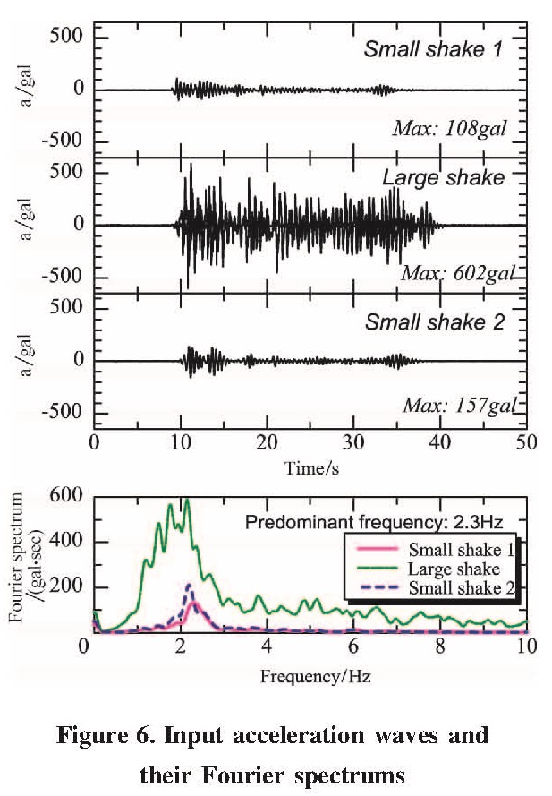
1.4 Input WavesGround motions based on the recordings during the 1940 El Centro earthquake were used for the random input wave in this experiment.Figure 6 is the input acceleration waves.The maximum acceleration was normalized to about 100 gal(called “Small shake 1”),about 600 gal(called “Large shake”)and about 150 gal(called “Small shake 2”)and used for the experiment.The influence of the ground deterioration was examined by the continuous dynamic loading using these three kinds of waves.This paper mainly discusses the behaviors of the models under Large shake.
All the results of the centrifuge tests are presented in terms of prototype scale,hereafter.
2 Experimental Results and Discussions
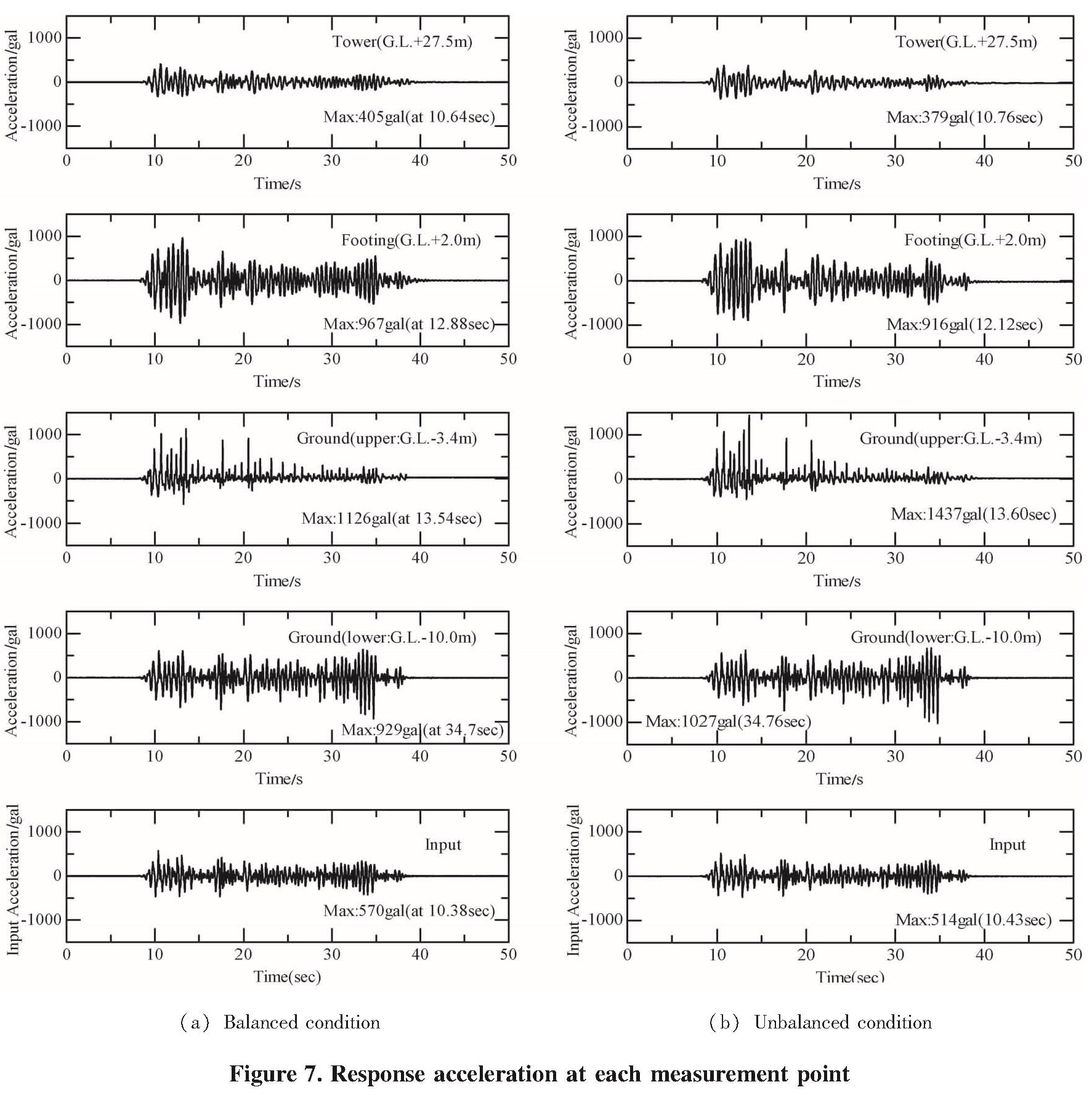
2.1 Response Acceleration WavesFigure7 shows the time histories of horizontal acceleration in both cases at all measurement points when inputting large shake.Measurement points were at the top of the tower crane,the footing and the model ground.These waves might be divided into 7~20 s(1st interval)and 20~40 s(2nd interval).The 1st interval contained a principal motion and the 2nd interval was a motion after the principal motion.The response acceleration at the top of the tower crane showed a similar tendency to that at the footing,although its amplification factor was lower.As for the response acceleration of the ground,the amplitude of acceleration decreased with the decreasing depth.The tendency was distinguished in the surface ground(G.L.-3.4 m)at the 1st interval because of the clay softening under cyclic loading.It should also be added that there were spiky waves observed in the surface ground(G.L.-3.4 m)in both cases.This may be explained by the collision between the pile and the ground.
2.2 Comparisons of Dynamic Characteristics between Various Weight Conditions of the Crane JibThe time histories of the horizontal displacement of the footing in both cases at Large shake are plotted in Figure 8.As for the vertical axis in this figure,the positive side means the deformation in the direction of the main jib.Note that the point where the footing displacement was measured 10 mm above the ground level.As shown clearly in the figure,in the case of the balance weight condition,the horizontal displacement of the footing was nearly zero.On the other hand,in the case of the unbalance weight condition,inertial deformation took place at the first interval.After the first interval which contained a principal motion,horizontal displacement of the footing could not be observed because measurement range was over.At the end of shaking,the observed permanent horizontal displacement of footing was about 150 mm in the direction of the main jib which was located at the heavy weight side.Then Figure 8b makes additional double integration of acceleration records on the footing(blue line).For the results of horizontal displacement of the footing,it appears that not only kinematic forces resulting from cyclic ground displacement but also inertial forces from the superstructure may come to play important roles.
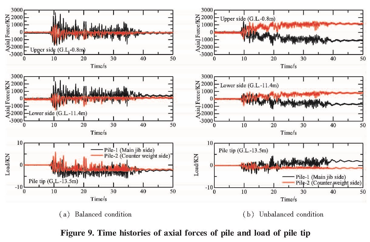
Figure 9 shows comparisons of the axial forces observed at piles in both cases.In the vertical axis,the positive side means the compression of pile.In addition,Pile-1 is on the side of the main jib and Pile-2 is on the side of the counterweight jib,respectively.In both cases,the axial forces of Pile-1 changed in the opposite phase to the axial forces of Pile-2.It means that rocking motion occurred in the motion of the superstructure.Additionally,the axial force of Pile-2 was much larger than that of Pile-1 at upper part of pile.In the unbalance weight condition,the residual axial forces recorded with Pile-1 and Pile-2 took place.In comparison with the result of the balance weight condition,it is obvious that the residual axial force at the pile in the unbalance case is larger than that in the balance case because of the overturning moment caused by unbalance weight condition for superstructure.
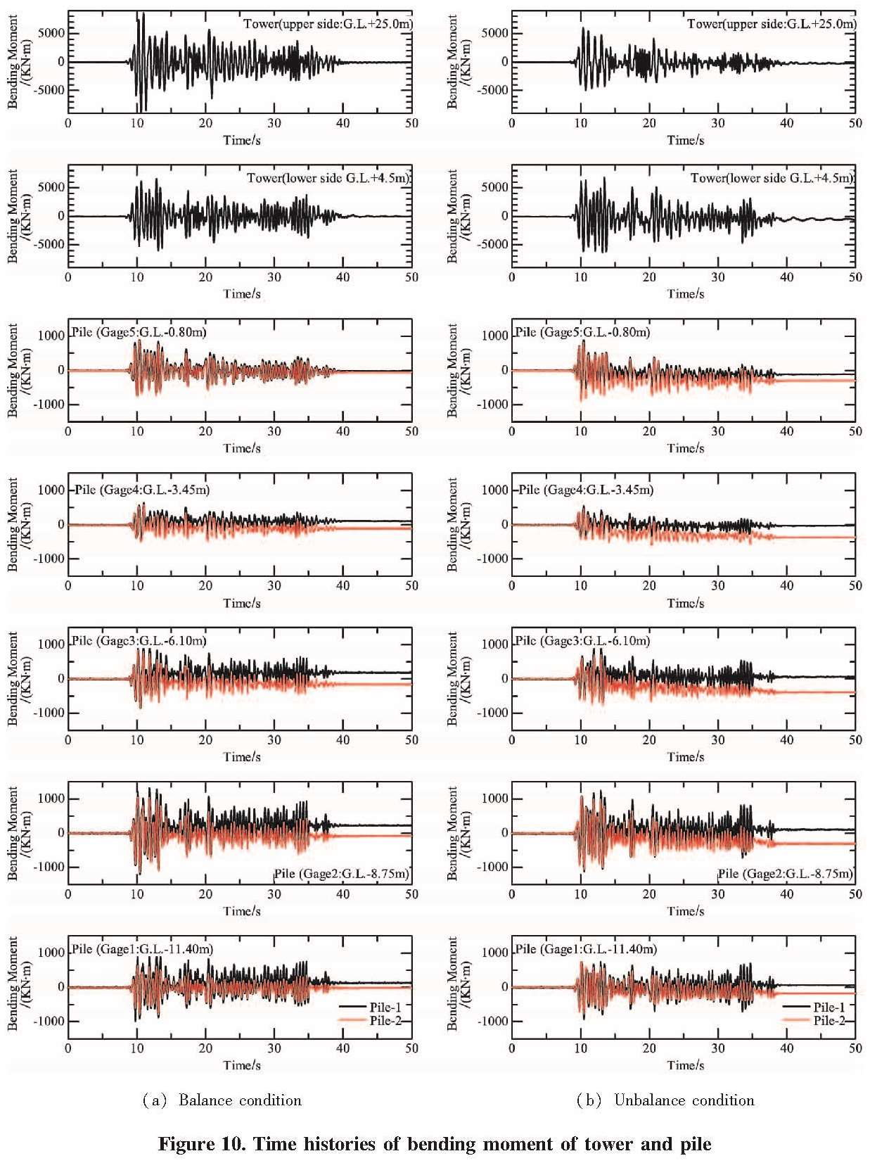
Figure 10 shows the time histories of bending moments in both cases at all measurement points,together with the locations of upper and lower part of the tower.In the unbalance case,the results show that the bending moment of the lower part of tower crane corresponds to the amplitude of the upper part of tower crane.On the other hand,the results in the balance case show that the bending moment of the upper part of tower crane corresponds to the amplitude of the lower part of tower crane.
In the case of the balance condition,the magnitude of the bending moment of Pile-1 was larger than that of Pile-2 at the middle part under the ground(G.L.-8.75 m).In both cases,it can be pointed out from the distributions that inertial forces from the superstructure mainly dominate.In such a case which the pile at the position of the middle part of under the ground is heavily damaged,there may be great risk in tilting failure of tower crane.The results also provided that it is important to consider the dynamic interaction between the piles and the ground.
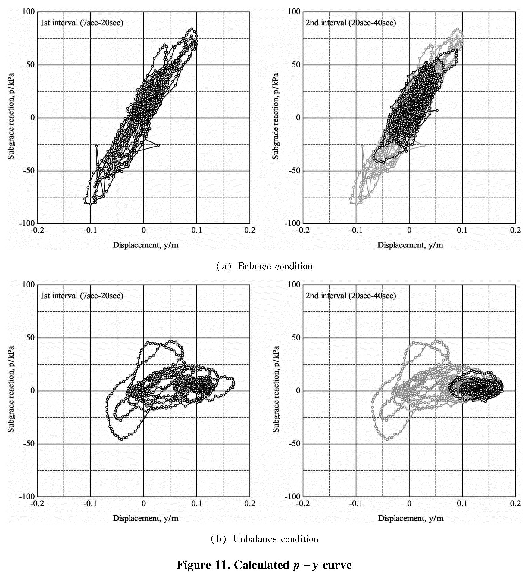
2.3 p-y CurveIn order to discuss soil stiffness transition during an earthquake,this study focuses on p-y behaviors by back-calculating the recorded bending moment distribution M(z)along a pile based on a simple beam theory according to the equations.In this study,four numerical differentiation methods were used to determine soil stiffness transition:weighted residual derivatives,central difference formulas,differentiation
of cubic spline interpolation functions,and differentiation of polynomial interpolation functions.Then,integrating to solve for p and y requires specification of two boundary conditions.The measured footing displacement relative to the container base was used for one of the boundary conditions and the pile tip displacement and moment was assumed to be zero for the other.
Figure11 shows p-y curve at G.L.-0.3 m in both cases.These p-y behaviors were divided into 1st interval(7-20 s)and 2nd interval(20-40 s),respectively; The observed p-y behaviors in the case of the balanced condition show a typical linear shape.Whereas the observed p-y curve in the case of the unbalanced condition follows a softening spring type shape to the stress strain curve during a cyclic triaxial test of soft clay.Furthermore,in the case of the unbalanced condition,it may not at the same point in horizontal space as when it detached,resulting in the shift in the axes of oscillation of displacement in Figure 11 b.
3 Conclusions
A series of centrifugal model tests verified the influence of weight condition of superstructure,which is the crane jib,on the dynamic characteristics of tower crane supported by a pile foundation in soft clay ground.The main knowledge which is clarified by the centrifuge experiment is as follows;
(1)As for the response acceleration of the ground,there were spiky waves observed in the surface ground in both cases
(2)For the results of horizontal displacement of the footing,it appears that not only kinematic forces resulting from cyclic ground displacement but also inertial forces from superstructure may come to play important roles.
(3)As for the response axial force observed at piles,it means that rocking motion occurred in the motion of the superstructure.Furthermore,it is obvious that the residual axial force at the pile in the unbalance case is larger than that in the balance case because of the overturning moment caused by unbalance weight condition for superstructure.
Consequently,in the case of seismic stability of tower crane,it is necessary to consider the interaction of the surface ground and the pile foundation.
Acknowledgment
Former Tokyo City University formerly known as Musashi Institute of Technology graduate students Mr.Masao Jingu and Mr.Naoyuki Itoh provided some of centrifuge tests,and supported some data processing.Authors would like to thank them.
- ARAI F,ITOH K,SUEMASA N,Katada T,et al.2006b.Dynamic response of tower crane with pile foundation[C]//International Conference on Physical Modelling in Geotechnics – ICPMG '06,Hong Kong.London:Taylor & Francis Group,971-974.
- ARAI F,KATADA T,SUEMASA N,et al.2006a.Seismic stability of Tower crane with pile foundation in loam ground[C]//First European Conference on Earthquake Engineering and Seismology 2006(1st ECEES):Joint Event of the 13th European Conference on Earthquake Engineering and the 30th General Assembly of the European Seismological Commission.Swiss Society for Earthquake Engineering and Structural Dynamics,768.
- HORII N,ITOH K,TOYOSAWA Y,et al.2006.Development of the NIIS Mark-II geotechnical centrifuge[C]//International Conference on Physical Modelling in Geotechnics – ICPMG '06,Hong Kong.London:Taylor & Francis Group,141-146.
- ITOH K,SUEMASA N,TAMATE S,et al.2004.Dynamic loading test for pile supported tower crane in soft clay[C]//Proceedings of the 13th World Conference on Earthquake Engineering,Vancouver B C,Canada.
- ITOH K,TOYOSAWA Y,Kusakabe O.2009.Centrifugal modelling of rockfall events[J].International Journal of Physical Modelling in Geotechnics,9(2):1-22.
- The Japanese Geotechnical Society.1995.Research committee on dynamic characteristics of clay[J].Cooperative study of strength of clay on the cyclic load,Tsuchi to Kiso,The Japanese Geotechnical Society,43,(5):79-82.
